
3D
Different Joist Types have their own material assignment in 3D.
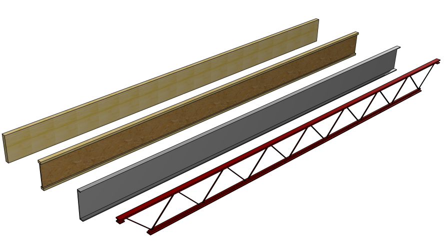
Beams
Beams display shaded in Floor System mode making them more prominent.
Curved Beams can be referenced by Floor Systems.
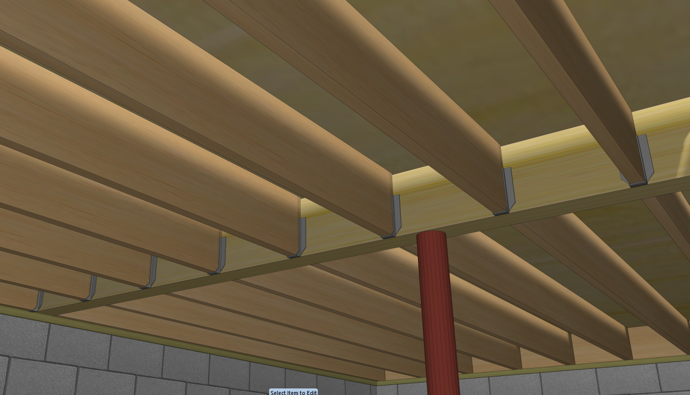
Joist Hangers
Joist Hangers can be made visible in 2D and extract in 3D.
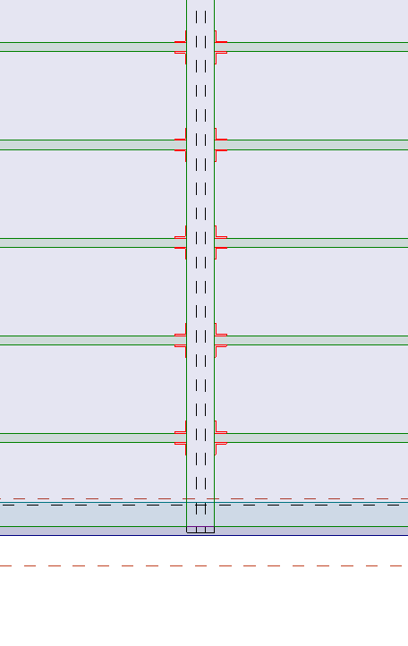
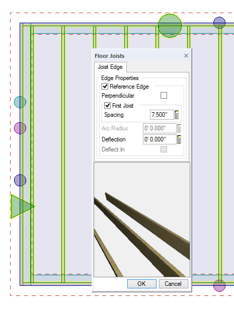
Joist Spacing
First Joist Spacing can be different than other Joist Spacing allowing joist to be position to avoid obstacles like plumbing and mechanical.
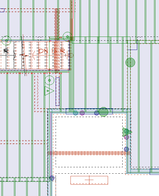
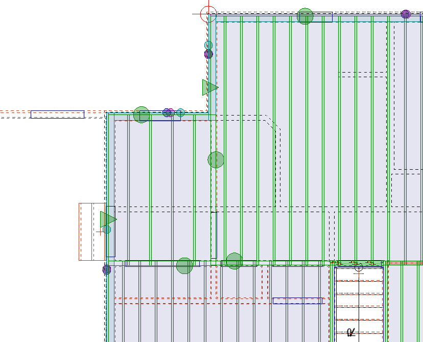
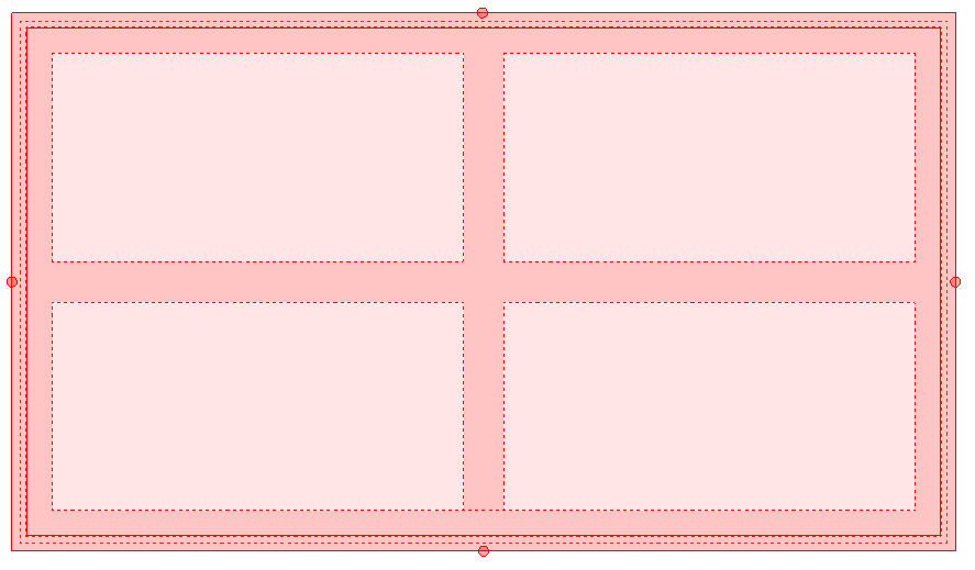
Overlay
Walls above the floor and below the floor system can be displayed.
The drawing pictured here shows walls below in dashed brown lines and the wall on the floor above in dashed black lines.
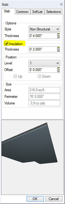
Slabs
Slab insulation thickness can be specified.
Slab thickness can be specified.
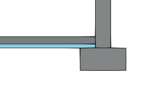
Slabs with recessed edges display a solid line to indicate the depression
Subfloor
Subfloor Area automatically subtracts holes in subfloor.
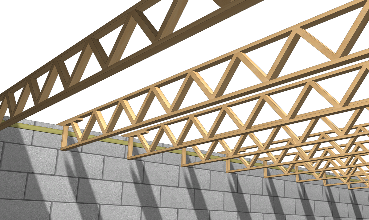
Truss
Drop Chord truss type added.
I have no idea how to add floors and a basement. I just have the main floor done. can anyone help?
This is from “Steps in creating a residential plan” in both your manual and the help file:
Steps in Creating a Residential Plan
Where to Start?
The section Drawing Management describes two methods that you may want to use to store and organize your drawings. As time passes, you will accumulate hundreds of drawings. In order to locate the drawing you want, be sure that you organize your drawings into a format suitable for your business.
1. Select Create a New Project from the Start Page, or select File ® New ® Folder and enter a name for the project.
Create the Main Floor Plan
1. A new drawing is already created for you in the Project.
· The main floor plan will be created in this Drawing.
2. Sketch in the exterior and interior walls.
· Choose the wall type you wish to use. For example, for exterior, use 2×4/Brick or 2×4/Siding.
· Sketch in the walls to the approximate length and position to form the room layout you are trying to achieve.
– Do not try to be precise at this time since later steps will add the precision.
3. Dimension interior and exterior walls.
· Use Auto Dimension to place dimension lines for exterior walls.
· Use the Dimension tool to scan in interior dimensions.
– These are working dimensions that you will use to accurately set the wall positions. Since you will remove them later on, you do not need to position them accurately.
4. Edit the wall dimensions to set walls in the exact position.
· Use the Edit command to set the exact position of each wall using the working dimensions that you added.
· Remember to work from one side of the floor plan to the other. For example, when editing horizontal dimensions, start editing on the left side and move towards the right side of the floor plan. When adjusting the vertical dimensions, start editing from the top and move to the bottom of the floor plan.
5. Add all windows and doors.
· Place the windows and doors (openings) in their approximate location. Do not spend time trying to get the openings in their exact location. Edit the dimensions that you place on the openings to quickly achieve this.
6. Erase the working dimensions.
· Many times the working dimensions that you have added to a drawing are not placed in the best location after the walls have all been relocated. In addition, new dimensions will be required to dimension the windows and doors.
· Use Auto Dimension to update the dimension lines for exterior walls. The existing exterior dimensions will automatically be erased and new dimension lines will be added.
· Interior dimensions must be manually removed and added again or existing interior dimensions must be manually relocated as needed.
– Since dimensioning is very quick and easy, you will probably find it faster to erase all the working dimensions and extensions using the Type Erase command and replace them using Auto Dimension for exterior walls and then rescan the interior Dimensions.
7. If necessary, set the exact window and door styles.
· Use the Edit function to do this.
· Use the Repeat Edit and Duplicate functions to quickly set similar windows and doors.
8. Set the exact window and door locations.
· Position the windows and doors accurately using the Edit function to adjust the dimension lines attached to each window and door.
9. Save your drawing using the Save command.
· In the event of a computer failure or if you want to revert back to an earlier design, you can easily retrieve saved versions of the drawing from the Recovery folder for the current folder.
10. Add details to your floor plan.
· Complete your design by adding details from the libraries of pre-drawn symbols and cabinets.
· Add electrical symbols and their connections.
· For common messages, add notation using the Speed Note libraries.
· As you add details, you may want to make minor changes to the floor plan to accommodate the cabinetry or appliances that you want to use.
· Add stairs and set them to the correct rise and run.
· Adjust dimension positions as necessary.
· Add reference points.
11. Save the drawing.
Create the Foundation Plan
If your design requires a foundation, you must create a new drawing for the foundation plan. To do this:
1. Use the Save As command to make a copy of the main floor plan in the same folder.
· This becomes a separate drawing.
· Name it, for example, Basement or Foundation.
2. Modify this copied drawing.
· Erase unneeded walls, openings, symbols, cabinets and so on.
· Use the Type Erase function to remove items by their type.
· Use Block Erase to remove all items within a specified area.
3. Change the remaining walls to the type used for the foundation.
· Use the Change Wall function to change all walls of the same type to the type needed.
· Use the Edit function to change individual walls.
4. If necessary, Edit the dimension lines to position the walls.
· Be careful not to move bearing walls since they must line up with any bearing walls on the floor above. When adding bearing walls you can use the edit function to set the Anchor option, then if you attempt to move a bearing wall a message will appear warning you that this wall is anchored.
5. Add support beams.
· Add any support beams that are required.
6. Add support posts.
· Use the Post (plan) function for this.
7. Add windows and doors to the foundation plan.
8. Add additional dimensions.
· You can choose to add additional dimensions for the objects you have added or you may prefer to erase all dimensions and re-dimension the plan as required.
9. Add details to the foundation plan.
· Complete your design by adding details using the symbol libraries.
· Add electrical symbols and add their connections.
· For common messages, add notation using the Speed Note libraries.
· Adjust dimension positions as needed.
10. Add the floor system.
· Select Floor System mode from the Status bar (or press ctrl + j).
· Use the Slab function to add concrete slabs in the basement and garage areas.
· Choose the type of slab you wish to use:
– Structural (monolithic) to support the outside bearing walls
– Slab footings for interior bearing walls
– Non Structural
11. Cleanup the flooring system by selecting the Cleanup button from the Toolbar (or press ctrl + c).
· Concrete slabs that you have added will snap to the walls. Structural slabs will snap to the outside of the wall while non-structural slabs will snap to the inside.
· The offsets of walls supported by the slab and any symbols you have added will be adjusted to position the item on top of the slab surface.
12. Set the slab to the proper offset.
· For single level foundations, leave the offset at 0″.
· For multi-level foundations, use Edit to set the level of each slab and the offset you wish to use for each level. As you adjust the offset of a slab all walls, stairs, and symbols supported by the slab will automatically be adjusted as well.
· Perform a cleanup.
13. Check the offset and height of the walls.
· Select wall Profile mode from the Status Bar to check the height, offset, and offset direction of the walls.
· Use the Edit function to adjust the offset of any walls that require adjustment.
· If stepped foundations are used the stepped wall must be divided into each step section. Use Part Erase to break the walls into stepped sections. The offset and wall height of each section must then be set using the Edit function. You can also use the Step Wall command.
14. Save the drawing.
Create the Second Floor Plan
If your design requires a second floor you must create a new drawing for the second floor plan. To do this:
1. Use the Save As function to make a copy of the main floor plan.
· This becomes a separate drawing.
· Name it, for example, Second Floor or Upper Floor.
2. Using the same steps you used to generate the foundation plan, modify this copied drawing to convert it to the second floor plan:
· Erase walls, openings, symbols, and other elements that are not needed.
· Change the remaining walls to the type used for the second floor.
· Draw any new walls or move existing walls as needed.
· Add new windows and doors as needed.
· Add additional dimensions as needed.
· Edit dimension lines to position walls accurately.
· Add details.
3. Save the drawing.
Complete the Main Floor Plan
We will now return to the main floor plan to add a flooring system and set up the wall offsets. To do this:
1. Select Floor System mode from the Status bar (or press ctrl + j).
2. Add sill plates, ring joists, and subfloor.
· By selecting the Ring + Plate + Subfloor command, all three can be placed at the same time.
3. Use Cleanup to position the sill plates, ring joists, and subflooring.
· When you press ctrl + c to cleanup the drawing, the sill plates, ring joists and subflooring are adjusted to line up with the outer edge of the wall studs.
4. Overlay the floor below.
· The objects you draw on a floor plan are supported by the flooring system for that drawing.
· Use the Overlay function to see the walls on the floor below (those, which will support the floor system).
· With the Overlay function you will see the supporting walls and beams as dashed black lines while the walls being supported are shown as dashed brown lines.
5. Add joist sections to span between supporting members.
6. Use Cleanup (ctrl + c) to snap the joists to the ring joists.
7. Use the Hole Rectangle or Hole Polygon commands to block openings for stairs and plumbing drops.
8. Add single joists where required to double up joists under bearing walls.
9. If the floor plan has more than one level, the offset must be set for the joists to allow the flooring system to sit on top of the walls of the floor plan below.
· To set the offset, use Edit to set the level of each joist set and the offset you wish to use for each level.
· The offset of the ring joists, sill plates, and single joists will be automatically adjusted as well.
· As you adjust the offset of the floor joist system, the walls, cabinets and symbols that rest on it will be automatically adjusted as well.
· Perform a cleanup.
10. Add cross-bridging.
· Use the Bridging function to add bridging if you wish to show cross-bridging on your floor joist plans.
· If you add bridging to your floor joist plan, your material list report will have a precise listing of the cross-bridging material.
11. Add ceiling board to your floor plan.
12. Select wall Profile mode from the Status Bar and check the offset of the walls.
· When the offset of the joists is set, the offset of the walls is adjusted automatically.
· Check the wall offset and use Edit to adjust any walls as necessary.
13. Save the drawing.
Complete the Second Floor Plan
If you have created a second floor you must now add a floor joist system and set the wall offsets for that floor.
· The steps used are the same as when completing the main floor.
· When setting the offsets for the second floor, remember that the offset is relative to the baseline, or zero.
Add a Roof Plan
A roof plan must be added to each floor that is covered by a roof. For example, the roof covering the second floor must be added to the second floor. If there is a garage area on the main floor that is not covered by the second floor, a roof section must be added to the main floor to cover this area. You can add these roof areas separately or you could use the Multi Floor Roof command to add the roof over the areas.
For each floor do the following steps:
1. Select Roof mode from the Status bar.
2. Use the automatic roof functions to add the roof plan for that floor.
3. When the roof plan has been designed, use the Profile function to check that the roof profile is correct.
4. Use the Bird’s Eye function to check that the roof is correct.
· Note: If the roof is correctly referenced to each wall, yet the roof plan is not correct, the reason may be that the wall offsets or wall heights are not set correctly. If the walls are not correct, you must return to the floor plan and make the necessary corrections.
5. Add the roof framing.
6. Save the roof plan for the floor.
Add the Cross Section Cut Lines
Before you can generate cross sections, you must place the section cut lines on the floor plan. These same lines will be used to indicate the point at which all the floors, including the roof above, will be cut when generating the automatic cross section.
Stack the Floors of the Building
When generating the automatic cross sections, elevations, and 3D views of the building, SoftPlan will build the sections and views from the bottom up using the floors you select. Use the Model section of the Navigation Window to assemble the floors:
· Drag and drop the lowest floor and drag and drop each floor in ascending order.
· Any roof plan that has been saved with the drawing will also be included with the drawing when it is selected.
Generate the Cross Section
Use the Cross Section feature to generate full cross section drawings of the plan you have created. These cross section drawings can be used to verify wall and joist offsets. To generate a cross section:
1. Select the cut line by which to generate the cross section from the Navigation Window.
2. A tab or new window is opened and the cross section drawing appears showing walls, joists, and roof.
3. Save the cross section by selecting Save As from the File menu, entering a name for the cross section drawing, for example Section A, and pressing the Save button.
4. Repeat above steps for additional cross section views.
Generate Elevation Views
The elevation feature allows you to generate exterior elevation views of the building. To generate an elevation view:
1. Select the direction from which you want to view the model from the elevation section of the Navigation Window.
2. An elevation drawing showing walls, windows, and the roof appears.
3. Use the Modify menu to change the appearance of items in the elevation, or you can return to the 2D drawing, make your changes, and then return to the elevation view and press the Regenerate button to regenerate the elevation.
4. Save the elevation by selecting Save As from the File menu, entering a name for the elevation drawing (e.g., Front View) and pressing the Save button.
5. Select Camera from the 3D menu bar to generate additional elevation views.
Complete the Cross Section and Elevation Drawings
SoftPlan can only generate the elevation and section drawing to the level of detail available from the floor plans and the roof plans. You may need to add additional details such as trim detail, notation, and dimensions. These additions are made in Drawing mode using the Symbol libraries, drawing tools, and notation tools.
Thanks for the top chord bearing trusses!
Will you be able to show top chord bearing on top of a central beam?
Yes.
Harry, Drop Chord Truss certainly names correctly what I am looking at. I was an Engineering Drafter for 9 years back in the middle ages and the nomenclature will stand up in Southeast Texas. You’all come see us, Ya Hear?
Would like it if hidden beams appeared different on the screen so that I could tell w/o editing them to find out.
Please create a suggestion at https://ww2.softplan.com/?page_id=818. That way the developers can sort through exactly what it is you are looking for.
The top chord (ya mispelled it) trusses will be sooooo helpful to us! Any chance you can snap railings to subfloor edges? Can you have floor mode show overlays while your drawing mode doesn’t – similar to how roof mode can do “multiple floor roof” so we don’t have to constantly turn overlays on and off (and to worry about them printing when not desired)?
Floor System mode can show an overlay while Drawing mode on the same drawing does not.
Love the overlay, hangers and slab insulation
So glad to the top chord bearing trusses added! Thank you developers!